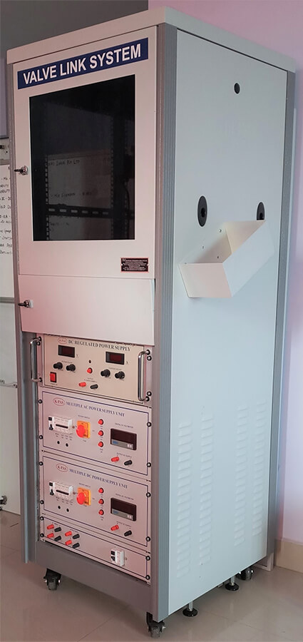
K-PAS Valve Link system is used to check the Valve such as control Valves,Regulators, Actuators, Isolation Valves and Solenoid Valves, where constant AC and DC Voltage is supplied Constantly to check the working condition of the unit and through the test. This is done for newly manufactured products as well as old ones to check the durability and the working condition of the Valves.
| Fixed Power supply |
|
| Variable Power Supply |
|
| High Voltage Power Supply |
|
| Input Voltage | 230V AC 50HZ |
| Output Voltage |
|
| Capacity | 0- 3 A DC |
- Digital Output Metering 3 Digit DPM
- Constant Voltage/Constant Current Operation
- High Stability and Close Regulation ±0.01%
- Proven Reliability and Endurance
- Remote Sensing Facility for Higher ratings
- Special voltage and current ratings available on request
K-PAS HV Tester is used to test battery or other such components and check the cut-off value or Break down Voltage. Every Electrical Apparatus or Machine is provided with insulation between live part and earth or between two different sections of live parts. As per the relevant is standard and Regulations of Electricity Rulers, these Insulations are required to be tested at High Voltage values recommended by applicable relevant standards.The Standard Specification for various Electrical Apparatus specifies Power frequency voltage withstand Test at different level depending upon working voltage of the Electrical Apparatus. It is observed from the various standards for Electrical Equipments that the Minimum Power frequency Voltage withstand Test Level for Electrical Insulation is 2KV for 1 minute. We have standardized our High Voltage Equipment at 5 KV in Aircooled Design with H.T.Current rating of 50mA. The Output of these High Voltage Tester are Single Phase 50 Hz.
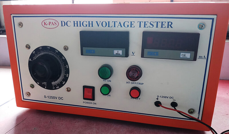
- Input Voltage : 230V AC 50HZ
- Output Voltage : 0-1250V DC
- Capacity : 0- 100 mA
- TRIP SOUND ADDED
- Digital Metered Display for Current and Voltage
- TRIP SOUND ADDED
- Digital Metered Display for Current and Voltage
- High Precision and Cut-off
- Long Durability
- Immediate service
CD Tester or cathodic disbonding tester is designed to test and accurately determine the characteristics of insulating coating systems applied over steel Purpose of coating system is to prevent corrosion that could occur in the underground pipeline services. Importance of coating inspection is therefore highly important. Underground pipes are coated and cathodically protected. Applied cathodic protection potentials may cause loosening of the coating, beginning at holiday edges. Spontaneous holidays may also be caused by such potentials.
Test method provides accelerated conditions for cathodic disbondment to occur and provides a measure of resistance of coatings to this type of action. Cathodic disbondment tester is used in civil engineering for evaluation of epoxy coated rebars to evaluate effect of cathodic protection on epoxy- coated rebar.
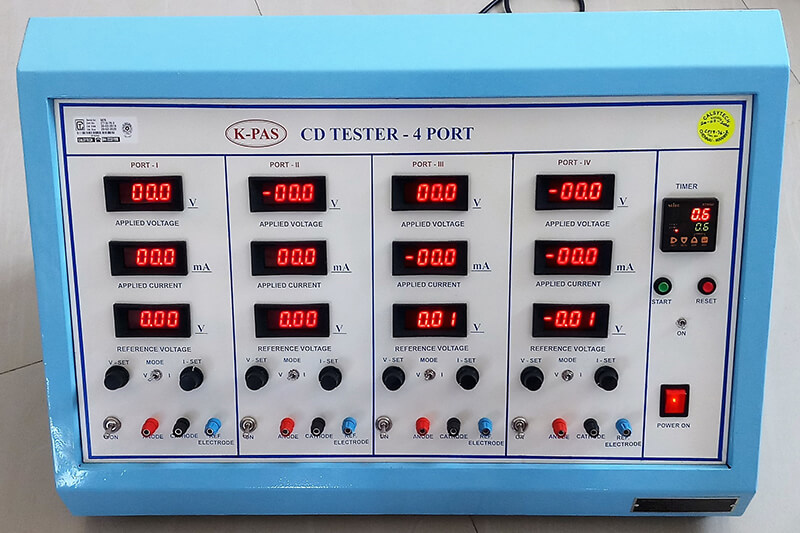
- User has options to choose Single ,Two,Three,Four ,Five Port and etc model while ordering CD Test Unit.
- User has option of adjustable knob for precision control of voltage.
- CD tester with 0-30.0 V ±0.2% with current range of 100 mA
- 5 set of reference electrodes ,Power cable comes along with the unit.
- User can select potentiostat channel by using toggle switch to see display of voltage, current.
CD Tester meets or exceeds the requirements of ASTM G8- Test methods for cathodic disbonding of pipeline coatings, ASTM G42- Standard test method for cathodic disbonding of pipeline coatings subjected to elevated temperatures, ASTM G95- Test method for cathodic disbondment test of pipeline coatings using cell method, DIN 30671 and EN 12068 standard, ISO 15711- Determination of resistance to cathodic disbonding of coatings exposed to sea water.
K-PAS Pulse-width modulation (PWM) is a modulation process used in most communication systems for encoding the amplitude of a signal right into a pulse width or duration of another signal, usually a carrier signal, for transmission. Used in Generic PWM duty cycle generator and Signal feedback across isolation barrier Pulse Width Modulation (PWM) of a signal involves the modulation of its duty cycle, to convey either information over a communication channel or control the amount of power sent to a load. PWM is employed in a variety of applications, ranging from measurements and communications to power control and conversion, mainly because of its low power, noise-free and low cost characteristics.
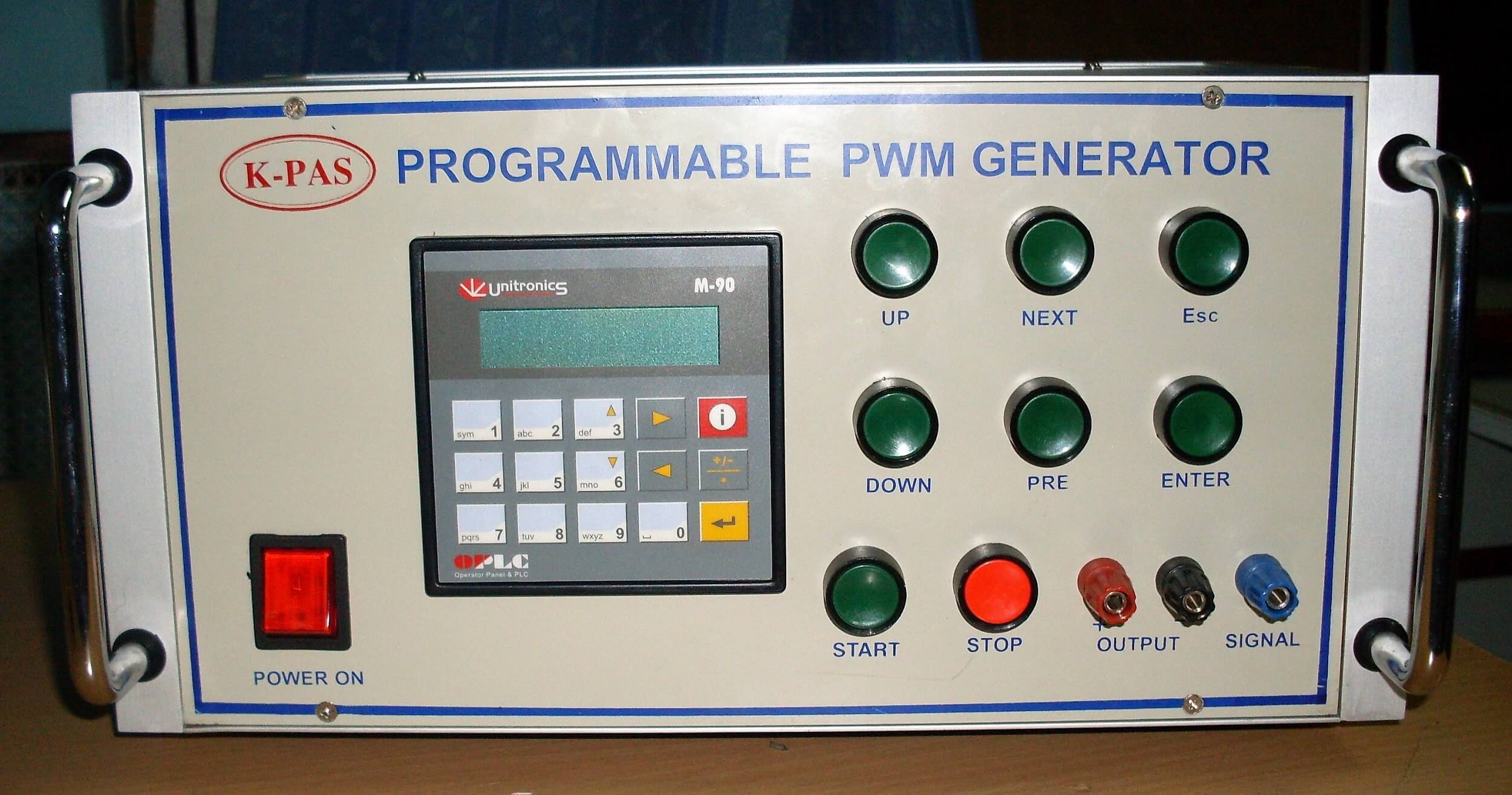
- 8V to 60V DC input voltage(customer requirements)
- 1% PWM duty cycle tolerance
- Programmable PWM frequency range: 100Hz to 50kHz
- Shutdown pin to minimize standby power
- As per request
K-PAS Functional Tester is used to operate the Control Valve which is used in petroleum plants whose operating Range upto 300 bar whereas the Functional Tester operates at 3-5bar to actuate the Control Valve.
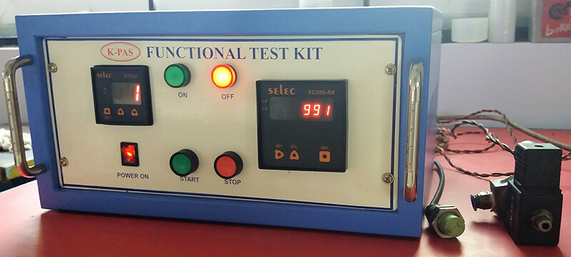
| Input Voltage : | 230V AC 50Hz |
| Operating Pressure : | 3-5 bar |
- Auto Sequence process based on Time and Position of the Valve
- Counter with Digital Display for Real time viewing.
- ON/OFF indication is provided.
