Our organization is also engaged in manufacturing and exporting an incomparable assortment of Fuel Cell Products. Comprising of products such as test station, data logging system and many more, the range is precisely manufactured making use of superior grade raw material and components, procured from eminent vendors of the industry. Prior to its delivery, the range is subjected to various checks and tests to ensure delivery of zero manufacturing defects only.
The best operation of the Fuel cell Test Station system is accomplished with an understanding of the basic operation of the system and its components. While many of these components are easily accessible or serviceable, they are selected to be highly reliable and have well understood operating characteristics. So that the user has a basic understanding of the function of these components Reactant Gas Flow One of the most important functions of the Station is to control the gas and fluid flow of reactants to the fuel cell under test.
This is accomplished through a carefully designed internal plumbing system. The components selected and their location provide control and safety for a wide range ofpotential conditions and hazards often encountered in fuel cell R&D. The components and their purposes are described in series change can be ramped at adjustable rate during the test procedure and can be automatically adjusted according to the load.
- Single Cell Test Station : 0.1 – 2 V – up to 10 Watts
- Fuel Cell Stack Low Power : 10 – 20 V – up to 500 Watts
- Fuel Cell Stack Medium Power Test Station : 20 – 40 V – up to 1500 Watts
- Fuel Cell Stack DMFC Test Station : 0.01 – 20 V – up to 300 Watts
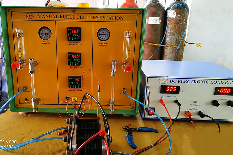
K-PAS DC Electronic Load unit is designed to load at constant Current which can be adjustable 0 to 15 Amps maximum, DC Electronic Load created through set of Resistors with bank of Transistors and control by an Electronic Circuit. This Equipment operates by 230V AC 50Hz. It also shows the digital Readout for DC Volts and DC-Amps & Calibrated for 5.00 V DC & 15.0Amps respectively.
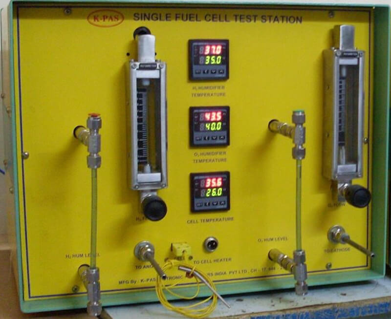
Fuel Cell Test station
| HYDROGEN FLOW | 0- 10 SLPM |
| OXYGEN FLOW | 0-10 SLPM |
| HUMIDIFICATION | 0-100 DEG |
| CELL HEATER | 35-60 DEG |
| HUMIDIFICATION HEATER | 500 WATTS |
| BOTTLE CAPACITY | 1.5 LITRE |
DC Electronic Load
| OPERATION | Constant Current |
| RANGE | 0.1V – 5V DC |
| CAPACITY | 0.0A – 15.0Amps |
| LINE REGULATION | 1% |
| LOAD REGULATION | 1% |
| PROTECTION | Constant Current |
| POWER INPUT | 230V AC 50Hz±10% |
| OPERATING TEMP. | 20 – 45 degrees |
- User has many options to choose between models.User has option of adjustable
- Load Bank Supplied with it
- Oxygen Flow andy Hydrogen flow can be based on Customer requirement
- Load Bank Capacity can be vary as per requirement.
- DIGITAL READOUT AND SETTING OF TEMPERATURE
- LEAKPROOF INTERNAL PLUMBING
- Fuse for protection
- Long lasting Life
- Immediate Service
The best operation of the Fuel cell Test Station system is accomplished with an understanding of the basic operation of the system and its components. While many of these components are easily accessible or serviceable, they are selected to be highly reliable and have well understood operating characteristics. So that the user has a basic understanding of the function of these components Reactant Gas Flow One of the most important functions of the Station is to control the gas and fluid flow of reactants to the fuel cell under test.
This is accomplished through a carefully designed internal plumbing system. The components selected and their location provide control and safety for a wide range ofpotential conditions and hazards often encountered in fuel cell R&D. The components and their purposes are described in series change can be ramped at adjustable rate during the test procedure and can be automatically adjusted according to the load.
- Single Cell Test Station : 0.1 – 2 V – up to 10 Watts
- Fuel Cell Stack Low Power : 10 – 20 V – up to 500 Watts
- Fuel Cell Stack Medium Power Test Station : 20 – 40 V – up to 1500 Watts
- Fuel Cell Stack DMFC Test Station : 0.01 – 20 V – up to 300 Watts
K-PAS DC Electronic Load unit is designed to load at constant Current which can be adjustable 0 to 15 Amps maximum, DC Electronic Load created through set of Resistors with bank of Transistors and control by an Electronic Circuit. This Equipment operates by 230V AC 50Hz. It also shows the digital Readout for DC Volts and DC-Amps & Calibrated for 5.00 V DC & 15.0Amps respectively.
Manual Fuel Cell Test Station with DC Electronic Load Bank
| Input Voltage | 230V AC 50HZ |
| Cell Voltage | 0.1V DC to 10 V DC |
| Output |
|
| Cell Heater | 0-100 °C |
| H2 Humidification | 0-150°C With Humidification Chamber |
| O2 Humidification | 0-150°C with Humidification Chamber |
Electronic Load Bank with Load and Ammeter
| Range |
|
| Watts | 50 Watts |
| Controller | Rotometer |
| Bottle Capacity | 500 ml |
| Model No | KM – 771 |
| Sl.no | 5550 |
| Make | K-PAS |
- User has many options to choose between models.User has option of adjustable
- Load Bank Supplied with it
- Oxygen Flow andy Hydrogen flow can be based on Customer requirement
- Load Bank Capacity can be vary as per requirement.
- DIGITAL READOUT AND SETTING OF TEMPERATURE
- LEAKPROOF INTERNAL PLUMBING
- Fuse for protection
- Long lasting Life
- Immediate Service
Fuel cell test stations including multiple electronic load channels, multiple gas flows, hydrogen with oxygen and hydrogen with air, multiple humidifiers with suitable configurations are available. For nitrogen purging provided in this system, back pressure regulation process also optional. Multiple channel voltage measurement modules are available for measurement of voltage of each cell in a stack Temperature Measurement. Temperature may be monitored at multiple points on each cell and at inlet-outlet points in the reactant transfer assembly Pressure Input Pressure measurement provides gas pressure Flow rate is controlled by manual rotameter or Programmable mass flow controllers are used to flow rate change can be ramped at adjustable rate during the test procedure and can be automatically adjusted according to the load.
- Single Cell Test Station : 0.1 – 2V – up to 10 Watts
- Fuel Cell Stack Low Power : 10 – 20V – up to 500 Watts
- Fuel Cell Stack Medium Power Test Station : 20 – 40V – up to 1500Watts
- Fuel Cell Stack DMFC Test Station : 0.01 – 20V – up to 300Watts
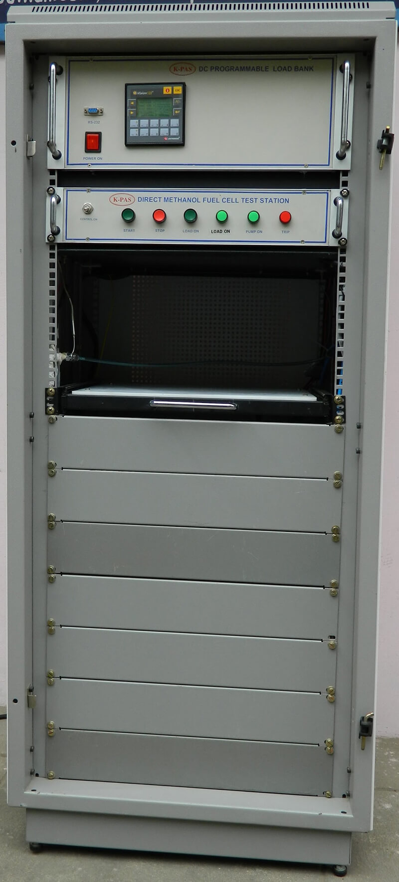
| CELL VOLTAGE RANGE | 0.1 TO 20VDC |
| MAXIMUM WATTS | UPTO 150 WATT |
| CELL CURRENT | 0 -20A |
| CONTROLLER | PC BASED |
| METHONAL FLOW | UPTO 10 SLPM |
CONTROLLED THRO DMFC PUMP
| AIR / OXYGEN MFC | UPTO 20 SLPM |
| CELL TEMPERATURE | UPTO 100 DEGREE |
| TEMPERATURE CONTROLLER |
|
- DIRECT METHONAL UNIT PROVIDES A CONTROLLED SOURCE OF HIGH PURITY METHONAL OR METHONAL/ WATER SOLUTION FOR TESTING OF METHONAL POWERED FUEL CELLS
- SAFE OPERATION WITH ANY METHONAL CONCENTRATION
- OPERATING PRESSURE UP TO 20 PSIG
- TEMPERATURE CONTROLLED METHONAL SUPPLY
- DIGITAL READOUT AND SETTING OF TEMPERATURE
- DIGITAL READOUT OF FLOW RATE
- STORAGE CAPACITY 3 LTRS
- LEAKPROOF INTERNAL PLUMBING
- AUTOMATIC OR MANUAL FLOW CONTROL
- AUTOMATIC – FLOW RATES UNDER CONTROL THROUGH COMPUTER
- HEATED METHONAL/OXYGEN TRANSFER LINES TO MAINTAIN FLUID TEMPERATURE
- PRESSURE : MAXIMUM BOTTLE PRESSURE 20 PSIG (2.3 BAR)
- FLUID CAPACITY : 3 LITER BOTTLE
- FLUID CONNECTIONS : ¼” SS 316 L TUBING CONNECTORS
- PUMP CHARATERISTICS
- METHONAL MIXTURE FLOW RATE 0.017 TO ml . 2slpm
- DIGITAL FLUID FLOW DISPLAY
- DIGITAL DISPLAY , METHONAL FLOW RATE MINIMUM RESOLUTION 0.0 ML/MIN
- DI GITAL DISPLAY ,OXYGEN/AIR FLOW MINIMUM RESOLUTION 0.01 ML/MIN
- PANEL INPUT/OUTPUT OUTPUT METHONAL REACTANT RETURN OF REACTANT TO BOTTLE PORTS FOR REFILL OF BOTTLE PORTS FOR DRAIN OF BOTTLE
- TEMPERATURE CONTROLLER METHONAL MIXTURE BOTTLE TEMPERATURE MATHONAL MIXTURE PUMPING LINE TEMPERATURE OXYGEN/AIR TUBE LINE TEMPERATURE DMFC CELL TEMPERATURE
- PHYSICALCHARATERSTICS 22U(H)X19”9W)X650(D)approx
- ELECTRICAL REQUIREMENTS 230 VAC /2A 50HZ 1 PHASE
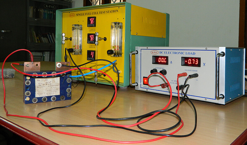
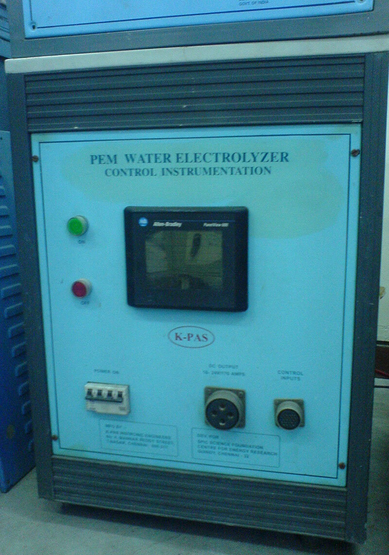
K-PAS has designed many a stand alone Test station of proton exchange membrane (PEM), DMFC fuel cell. The test station to provide a right solution for fuel cell research and addresses all aspects of handling and testing of PEMFC. Fuel cell test stations manual electronic load, hydrogen and oxygen individual humidifiers. For nitrogen purging provided in this system, Temperature Measurement. Temperature may be monitored each cell and at inlet-outlet points Input Pressure will be 2 bar maximum Flow rate is controlled by manual rotometer.
- Single Cell Test Station : 0.1 – 2V – up to 15 Watts
- PLC based control system to control all voltage, current, temperature,safety and gas air flow required parameters
- Power ratings range from 10 W to 10 KW, and are available in 10 Watt increments. Models are available with 12V, 24V,48V, 60V, 100V, 300 or 500V voltage rating
- Variable current ratings up to 1000A
- No of Cell Voltages – up to 100
- No of Temp. cells – up to 100
- This unit had gas humidification, gas heater and water leveling. temperature control & a bubbler type humidification.
K-PAS has designed specifically for the Test station of proton exchange membrane (PEM), fuel cell. The test station to provide a right solution for fuel cell research and addresses all aspects of handling and testing of PEMFC that are housed in a standard rack system. Fuel cell test stations including multiple electronic load channels, multiple gas flows, hydrogen with oxygen and hydrogen with air, multiple humidifiers with suitable configurations are available. For nitrogen purging provided in this system, back pressure regulation process also optional. Multiple channel voltage measurement modules are available for measurement of voltage of each cell in a stack Temperature Measurement. Temperature may be monitored at multiple points on each cell and at inlet-outlet point in the reactant transfer assembly Pressure Input Pressure measurement provides gas pressure Flow rate is controlled by manual rotometer or Programmable mass flow controllers are used to flow rate change can be ramped at adjustable rate during the test procedure and can be automatically adjusted according to the load.
- Single Cell Test Station : 0.1 – 2V – up to 10 Watts
- Fuel Cell Stack Low Power : 10 – 20V – up to 500 Watts
- Fuel Cell Stack Medium Power Test Station : 20 – 40V – up to 1500Watts
- Fuel Cell Stack DMFC Test Station : 0.01 – 20V – up to 300Watts
- Power ratings range from 10W to 10KW, and are available in 10 Watt increments.
- Models are available with 12V, 24V, 48V, 60V, 100V, 300 or 500V voltage rating current ratings up to 1000A.
- Control is either by a front panel potentiometer or a 0 to +10 V analog control signal on standard units
- Line Voltage-230VAC 50 Hz standard PLC based control system to control all voltage, current, temperature,safety and gas&air flow required parameters
- No of Cell Voltages – up to 100
- No of Temp. cells – up to 100
- Pressure H2 /O2
- Cell Voltage
- Stack Voltage
- Temp – Channel
- Voltage Channel
- Stack Current
- Stack Temperature
Fuel cell test stations including multiple electronic load channels, multiple gas flows, hydrogen with oxygen and hydrogen with air, multiple humidifiers with suitable configurations are available. For nitrogen purging provided in this system, back pressure regulation process also optional. Multiple channel voltage measurement modules are available for measurement of voltage of each cell in a stack Temperature Measurement. Temperature may be monitored at multiple points on each cell and at inlet-outlet points in the reactant transfer assembly Pressure Input Pressure measurement provides gas pressure Flow rate is controlled by manual rotometer or Programmable mass flow controllers are used to flow rate change can be ramped at adjustable rate during the test procedure. Main feature is capacity of 100W to 1200W.
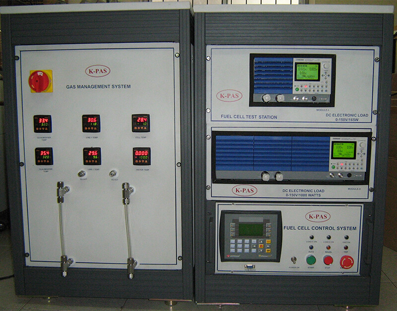
Fuel cell test stations
| Number of cells Monitoring | 1 – 40 |
| Cell voltage | 0 – 1.0 V |
| Stack voltage/Current | 0.1- 40.0 V/0-200 A |
| Gas flow Hydrogen | 0 – 10/upto100 slpm |
| Gas flow AIR/ Oxygen | 0 – 20/upto 200 lpm |
| Humidification H2 | RH 70-90 % |
| Humidification O2 | RH 70-90 % |
| Temperature monitoring | 5 – J-type |
| Data loggingthroscada | Thro PC |
V/I/FLOW/TEMP/PRESSURE/
| Control system | Thro PLC |
| ON /OFF Control | Thro solenoid |
| Pressure measurement | Thro Transmitter |
| Software | Windows based/LAB VIEW |
- GAS MANAGEMENT SYSTEM
- CELL HEATING THRO TEMP CONTROLLER WITH SSR
- HYDROGEN FLOW THRO MASS FLOW CONTROLLER
- OXYGEN FLOW THROUGH MASS FLOW CONTROL
- HYDROGEN & OXYGEN HUMIDIFICATION SYSTEM
- DC ELECTRONIC LOAD(CV/CC/CR)
- DATA LOGGING THROUGH PC
